Basic Principles of Transducer
Basic Principles of Transducer
 |
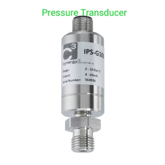
| Pressure Transducer |
The task of a process control system is to control the physical parameters like force, pressure, level etc and to maintain their value near the desired value.This is because the physical parameters may vary due to disturbances.
To maintain these parameters at a required level certain corrective action requires to be taken.
Fig. shows a process control loop.
 |
| Process control loop |
The process control loop consists of four blocks process,parameter measurement,
control element and controller.
control element and controller.
It is essential to measure the actual value of parameter P to achieve proper feedback.
Nowadays most of the controllers are electronic and hence they require an electrical input. Thus,the feedback signal is required in electrical form.
The measurement block includes two functions like to measure the parameter and to produce a suitable analog signal in electric form.
Sometimes the parameter measurement blocks produces non electric signals.Hence,we require a device that will convert this non electric signals to an electric signal.
Define transducer:
Transducer is converts a physical quantity to be measured into an equivalent electrical signal(voltage or current).
The physical quantity to be measured is like temperature,pressure,displacement,
vibration, flow, etc.
vibration, flow, etc.
The electrical signal obtained from the transducer is then used to control the physical quantity automatically and/or to display the same,as shown in Fig.
 |
| Transducer |
A transducer is also called as a pick up element.
It contains two parts that are closely
related to each other i.e the sensing or detecting element and the transduction element.
related to each other i.e the sensing or detecting element and the transduction element.
The sensing or detecting element is called as the sensor.It is a device producing measurable response to change in physical conditions.
The transduction element who converts the sensor output to suitable electrical form.
Fig. shows block diagram of transducer.
 |
| Transducer block diagram |
Generally the range of electrical signal used is 0 to 5V or 4 to 20 mA,4 to 20 mA range is commonly used to represent an analog signal.
A current of 4 mA represents zero output while a current of 20 mA represents a full
scale value.The zero condition represents open circuit is the transmission line. Hence,the standard range is offset from zero.
scale value.The zero condition represents open circuit is the transmission line. Hence,the standard range is offset from zero.
Sometimes the transducer is a part of system and works with other elements to achieve desired output.This kind of circuit is called as a signal conditioning circuit.


Comments
Post a Comment