Posts

Detail of Electric Shock

  Electric Shock Reasons for Getting Electric Shocks. The human failure in handling the electrical components or repairing the distribution system without switching off the supply, the ultimate effect of electric shock on human body  may be death.  Electric shock may result in:  Fibrillation of heart i.e. damaging the heart to small pieces causing the stopping of breathing. Stopping of breathing action due to blockage in the nervous system causing respiration difficulties.  Local high heating or burning of the body due to sparking.  Death of a person. First cause is dangerous and may put to death of person. Due to cause second and third  there is a possibility of rescuing a person. When an electric shock by human, the current passes through the body. Strength of current passing through the body may result as shown below   Current and shock effect 1 mA.  -  Perceptible,No-pains. 1-4 mA -  Tolerable, Not painful,Can be sensed. 4-...

Safety Signs and Symbols used in Industries

Image
 Industrial  Safety signs: Warning sign - Warning sign a sign giving warning of hazard or danger Overhead load - Overhead load There material handling going by Crain overhead Caution - Caution There is obstacle in the way Flammable material The material flammable. Direction signs - Direction signs Used for route direction Raised platform or height restriction - Emergency fire exit - Emergency fire exit First-aid facility - First-aid facility Fire extinguisher - Fire extinguisher Different types of fire classes and their prevention: Class A Fires - Class A Fires  Fire involving combustible material like wood, paper, cloth, rubber, plastic requiring the heat absorbing effects of water, water solutions. Class B Fires - Class B Fires This type of fire involves flammable or combustible liquids greases, petroleum products and' similar materials for extinction, a blanketing effect is essential. Class C Fires - Class C Fires Which involves the flammable gases, substan...

Basic Detail of Power Factor

Image
  Power Factor What is Power Factor ? It is the ratio of the active power of the fundamental wave the apparent power of  the fundamental waveform    Cause:    Inductive load which cause large difference of phase angle between current and voltage,Varying load,  industrial heating furnace, harmonic currents, electrical discharge lamp, AC motor, arc welder, furnaces, fluorescent lighting and air conditioning. Effect: overheating of motor and poor lightening.    Power factor correction: This is normally achieved by the addition of capacitors to the electrical network which compensate the active power. To reduce losses in the distribution system, and to reduce the clectricity bill, power factor correction, usually in the form of capacitors, is added to neutralize as ch of the magnetizing current as possible. Capacitor included leads the voltage, producing a leading power factor. The corrected power factor will be 0.92 to 0.95. Why to improv...

Basic Principles of Transducer

Image
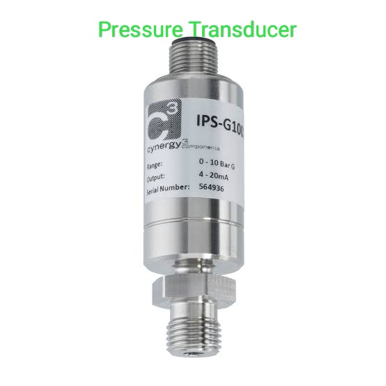
Basic Principles of Transducer Pressure Transducer The task of a process control system is to control the physical parameters like force, pressure, level etc and to maintain their value near the desired value.This is because the physical parameters may vary due to disturbances. To maintain these parameters at a required level certain corrective action requires to be taken. Fig. shows a process control loop. Process control loop The process control loop consists of four blocks process,parameter measurement, control element and controller. It is essential to measure the actual value of parameter P to achieve proper feedback. Nowadays most of the controllers are electronic and hence they require an electrical input. Thus,the feedback signal is required in electrical form. The measurement block includes two functions like to measure the parameter and to produce a suitable analog signal in electric form. Sometimes the parameter measurement...

Classification of Instrumentation System

Image
Classification of Instrumentation System Instrumentation system Null and Deflection type Instruments: Deflection type instruments: The instruments in which deflection of the instrument forms the basis of measuremenl are called as deflection type instruments. The example of deflection type instruments is the permanent magnet moving coil (PMMC) ammeter. PMMC AMMETER The deflection of the coil is proportional to the current that is to be measured. Torque Td, that acts on the moving coil is proportional to current.The opposing effect is produced by a spring, having torque Tc which is proportional to the deflection. When the spring is balanced Tc=Td. The value of the current depends on the deflection.Thus,the value of the measured quantity depends upon the calibration of the instrument. Null type Instruments The instrument in which, a null or zero indication will lead to the determination of the magnitude of the measured quantity such instruments are c...

Active and passive Instruments

Image
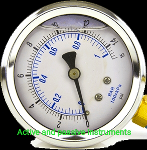
Active and Passive Instruments: Active and passive Instruments Passive Instruments: The instruments where the output is produced completely by the quantity that is measured are called passive instruments. The example of passive instrument is a pressure gauge.Fig  shows a pressure gauge. Passive  Instrument As the pressure in the liquid changes, the piston moves.The pointer is connected to the piston. No other source of energy is used. The liquid pressure is the only source. Thus,the piston and pointer movement while measurement is entirely dependent on the liquid pressure. Active Instruments: Active instruments are the instruments in which the quantity to be measured activates the magnitude of external power input source that produces the measurement. The liquid level indicator is an example of an active instrument.Fig.1.4.2 shows a liquid level indicator. Active Instruments The power source is required in or...

Instrumentation System

Image
Functional elements of an Instrumentation System: Instrumentation system Any instrumentation system can be described with the help of a block diagram.The block diagram of an instrumentation system describes the essential elements and their functions in a measuring system. Fig. shows the block diagram showing the functional elements of an instrumentation system.                     Instrument system The elements can be grouped as: Primary sensing element. Data conditioning element. Data presentation element. Each element comprises of a number of distinct components that perform a particular function in the measurement procedure.The function of each element is important.  Primary Sensing Element: To the primary sensing element the quantity to be measured is applied.e.g.in an ammeter, coil carrying current to be measured is a primary sensing element. Generally a transducer follows a primary sensing e...